Welcome, Guest. Please login or register.

Author Topic: DIY cycle completion mosfet?  (Read 21089 times)

T6e9a

  • Trade Count: (10)
  • Sr. Member
  • ****
  • Posts: 1293
    • View Profile
DIY cycle completion mosfet?
« on: March 18, 2016, 02:47:08 PM »
I've been pondering the idea of how to build or set up a mosfet/trigger unit so that it effectively has cycle completion.

What I mean by that, is pull the trigger for a split second or hold it down(in semi at least) and it will always finish a complete cycle.

I've been wanting to do this on my own as opposed to buy programable or other drop in mosfets.

My thoughts so far is that it would need the trigger switch to engage the cycle and then a switch associated with the cutoff lever to indicate when the cycle is complete.

Past that, I have no idea what other types of chips or electrical components would need to be wired up to offer the full functionality of the idea.

That's where hopefully the community might be able to chime in.
Offering airsoft repair, upgrades, tuning and customization, check out: Tange Six Airsoft Teching Facebook
Check out what I have for sale: Tango Six MIA sale thread

luke213

  • Administrator
  • Trade Count: (2)
  • Old school member
  • *****
  • Posts: 2979
  • Lukas Adams
    • View Profile
    • Adams Holsters
Re: DIY cycle completion mosfet?
« Reply #1 on: March 18, 2016, 03:14:21 PM »
I dig the idea allot, it goes along with my long term idea I thought about having a means to make the trigger actually sprung with a sear rather than a switch like they are now. Then the cycle would reset the trigger somehow but I haven't really set down to try and iron out the engineering. Just always been a pet peeve of mine with AEG's in general.

I'd be interested to see how it works out though, not a clue how to do it electronically I was thinking mechanically;)

Luke
xaos - "298,000 yen for a complete gun. How much is that in real money?"

kjones734

  • Trade Count: (2)
  • Old school member
  • *****
  • Posts: 1950
    • View Profile
Re: DIY cycle completion mosfet?
« Reply #2 on: March 18, 2016, 04:08:22 PM »
I am a electrical engineering student that is nearly graduated. I should be able to help you out a little bit. The first idea that popped into my head is using a 555 timer ic chip in monostable mode also known as a " one shot" (google that term for more info). basically a one shot will produce a "high" signal when ever it receives a input such as you pulling the trigger. How long it stays high will depend on the resister and capacitor values that you pick, I would recommend a variable resistor so you can tweek it to how long you need for a full semi auto completion.

So you would want to hook the trigger to the input of the 555 one shot, once you pull the trigger you get a high signal. You would then want to feed the one shot signal into the mosfet gate. the high signal from the one shot will open the mosfet and make the gun fire, the mosfet will turn off when the one shot signal drops back to low ( again this depends on how you have your  values of you resistor and capacitors)

A one shot will also allow full auto if you hold the trigger, since it will make the output signal high as long as the input is high (from the trigger).

I am actually kinda bored right now so I may draw up a schematic for you but no promises.


Here is a very good tutorial on the 555 one shot timer.

http://www.electronics-tutorials.ws/waveforms/555_timer.html
« Last Edit: March 18, 2016, 04:12:16 PM by kjones734 »

luke213

  • Administrator
  • Trade Count: (2)
  • Old school member
  • *****
  • Posts: 2979
  • Lukas Adams
    • View Profile
    • Adams Holsters
Re: DIY cycle completion mosfet?
« Reply #3 on: March 18, 2016, 04:11:49 PM »
Now I'm not an electronics guy at least not in the component sense;) I've been a computer guy all my life, but none the less. I'm not sure I understand the high/low signal part and maybe your saying what I started thinking when reading your post.

The motor should draw more current under load, it should really only be under load when pulling the spring. There should be a gap between high and low load IE current on the motor between each cycle. Would it be easier to somehow monitor the current and when it drops down as the spring releases to cut the current there. Then start the cycle again once you pull the trigger again?

Again that might just be exactly what your talking about but in my own terminology;) Just curious.

Luke
xaos - "298,000 yen for a complete gun. How much is that in real money?"

kjones734

  • Trade Count: (2)
  • Old school member
  • *****
  • Posts: 1950
    • View Profile
Re: DIY cycle completion mosfet?
« Reply #4 on: March 18, 2016, 04:19:52 PM »
Sorry, I should of explained high and low, I dont expect anyone to know the electronics technical terms. 95% of electronics work on 5 volts. although alot of things can take more then 5 volts as the input. when I say "high" I mean the 555 one shot is going to output 5 volts. when I say low it means it is outputting 0 volts. The high (5 volts) output signal from the 555 will get fed into the gate pin of the mosfet ( this is what controls the flow of the electricity in the mosfet) this high signal will allow for the mosfet to open and let the electricity from the battery flow to the motor. This circuit does not monitor anything, it simply waits for you to pull the trigger, then sends a high 5 volt signal for a length of time determined by the values of the resistor and capacitor, then goes back to waiting for you to pull the trigger again.

luke213

  • Administrator
  • Trade Count: (2)
  • Old school member
  • *****
  • Posts: 2979
  • Lukas Adams
    • View Profile
    • Adams Holsters
Re: DIY cycle completion mosfet?
« Reply #5 on: March 18, 2016, 04:23:12 PM »
Ok that's more what I was thinking initially when I read it, basically a timer circuit so it sends current for a set number of MS then cuts off. Which I can see working so long as the cycle length is the same, but wouldn't it be a problem with it getting out of sync. IE as the battery discharges the length of the cycle will change slightly, which would eventually I think lead to off cycle firing IE half pull etc. I could be wrong here just the first thing that pops into my head.

Would it be possible with fairly simple electronics do the monitoring type of setup I described above? Maybe it's too complicated etc I'm not sure. But it seems like a simple check and balance type of system that doesn't require a second sensor on the cut off lever since you could use the voltage/current change to trigger the end of the cycle.

Luke
xaos - "298,000 yen for a complete gun. How much is that in real money?"

kjones734

  • Trade Count: (2)
  • Old school member
  • *****
  • Posts: 1950
    • View Profile
Re: DIY cycle completion mosfet?
« Reply #6 on: March 18, 2016, 04:29:13 PM »
it could get out of sync for sure. Im not sure how bad it would get, I would think based on the discharge curve of a battery that you would not have any issues until the battery gets very close to dead. A circuit that monitors the current based on load of the motor pulling back the spring is possible but it will require me to think about it for a while and will not be as simple as the 555 one shot circuit. Ill ponder the idea for a while and let you know if I am able to think of something that is simple enough for you to build. I know I could do it with a micro sized arduino but that will require programming and at that point you might as well just buy one that is already pre built unless you are looking for the fun of the project.

luke213

  • Administrator
  • Trade Count: (2)
  • Old school member
  • *****
  • Posts: 2979
  • Lukas Adams
    • View Profile
    • Adams Holsters
Re: DIY cycle completion mosfet?
« Reply #7 on: March 18, 2016, 04:32:49 PM »
My theory was mostly that it might be easier than doing it the way T9 described up above but I could be wrong. I'd still be interested if you came up with a way to do it. I'm not opposed to learning how to program an arduino box I've considered those in the past for non airsoft related projects but if I did go that route for anything it would be way down my todo list just because my time is super freaking limited these days unless it's work related;)

Luke
xaos - "298,000 yen for a complete gun. How much is that in real money?"

kjones734

  • Trade Count: (2)
  • Old school member
  • *****
  • Posts: 1950
    • View Profile
Re: DIY cycle completion mosfet?
« Reply #8 on: March 18, 2016, 04:43:44 PM »
If you know how to program in "C" then you can program a arduino. You just use the arduino software and write your program then you upload it and wire what ever you want to the arduino and your done. arduinos make things very easy.

luke213

  • Administrator
  • Trade Count: (2)
  • Old school member
  • *****
  • Posts: 2979
  • Lukas Adams
    • View Profile
    • Adams Holsters
Re: DIY cycle completion mosfet?
« Reply #9 on: March 18, 2016, 04:45:09 PM »
I don't never been much for programming in typical languages done little with it over the years learned as needed. That said I'm sure I could learn it at least in a passable fashion fairly quickly. I just always found programming boring so I tended to have others do that part of jobs in the past;)

Luke
xaos - "298,000 yen for a complete gun. How much is that in real money?"

Snarf

  • Trade Count: (2)
  • Sr. Member
  • ****
  • Posts: 664
    • View Profile
Re: DIY cycle completion mosfet?
« Reply #10 on: March 18, 2016, 11:05:42 PM »
I have been thinking about something like this a lot recently too. Here's a suuuuper rough ms paint schematic:


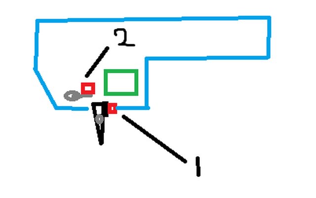
This is basically T6's idea I think. The red squares are switches; switch 1 is the trigger and switch 2 is the cutoff lever. Switch 2 is closed by default, and switch 1 closes when the trigger is pulled. When the cutoff lever is activated, switch 2 opens the circuit so the motor temporarily stops. The trick is, when the cutoff lever comes back, you don't want the circuit to close again.

Kjones, is there some kind of gate that will only become true once switch 1 is opened and closed again? If so, that should allow semi-auto to work.

Quick edit for detail:
I've done a bit of looking online for components (disclaimer: I have basically no experience with electronics) and I found some micro push buttons that could work since they're the right size. However, they can only handle around .2 amps, which is bad. Luckily, with a mosfet the switches shouldn't be getting a lot of current, right? Most of it goes through the fet I think, but actual quantities are important here. Also, I don't know how mechanically reliable those microswitches are (the Ares microswitch trigger was notoriously unreliable if I remember right).

Double edit because I read more of the thread:
I don't think an arduino would be good for a final version because they are a bit too big to fit in a gearbox, but maybe you could design a PCB that fits? The arduino would be great for prototyping the software though. Obviously a fully Computerized integrated fet is possible (spectre) but that kind of takes the cheap and simple part out of the whole concept. In my opinion, a combination of simple electrical switches and the existing mechanical parts would be ideal. That way you improve the normal AEG trigger, but you don't have to worry about sector gear sensors and microprocessors.
« Last Edit: March 18, 2016, 11:35:36 PM by Snarf »

kjones734

  • Trade Count: (2)
  • Old school member
  • *****
  • Posts: 1950
    • View Profile
Re: DIY cycle completion mosfet?
« Reply #11 on: March 19, 2016, 10:32:45 AM »
Ive been thinking about this and I realised that there is no need to worry about a cut off for semi since the gearbox already cuts off via the cutoff lever. When you shoot your stock aeg in semi if you pull and hold the trigger your gun will only fire no matter how long you hold the trigger. So there is no need to worry about adding anything to cut off the flow of electrons. A simple mosfet will be sufficient. The only reason the prebuilt mosfets have a timer feature is so you can fire 3 round bursts. Or so you can fire semi while in full auto and have the option to hold the trigger for full auto.


As to the ardrino they make small ones that are about a squre inch and cost about $2. You would not install that inside the gearbox, it would be inline where ever you store your battery.

T6e9a

  • Trade Count: (10)
  • Sr. Member
  • ****
  • Posts: 1293
    • View Profile
Re: DIY cycle completion mosfet?
« Reply #12 on: March 19, 2016, 01:37:04 PM »
I have actually set up a trigger switch exactly like that which Snarf described. I actually tried to replicate the design of Devan Clark CIA's "hair trigger housing" or whatever he called it. Same button layout.With just a mosfet hooked up, it didn't over current or melt any of the switches, due to the low gate voltage, but it also just shot in full auto, sort of to be expected.

 I was also considering pretty much redesigning the trigger mech area, with a micro switch for the trigger, and in a redesign, i would have room to have all of the mosfet components right in that area (at least in V2 gearbox for right now) with the ability to be front or rear wired, and not have to worry about gate wires and inline mosfets gumming up battery space.

The button for the cutoff would indicate the mechanical completion of a cycle, and figured that could be used with some other simple component.

I'll definitely look into the 555 one shot and see what that can do. But i would like to avoid anything timed, as timing based would change mechanical outcome between battery voltages and such. I'm looking for something fairly universal.

Good input so far guys, i like it!

Offering airsoft repair, upgrades, tuning and customization, check out: Tange Six Airsoft Teching Facebook
Check out what I have for sale: Tango Six MIA sale thread

zephurah

  • Trade Count: (0)
  • Full Member
  • ***
  • Posts: 221
    • View Profile
Re: DIY cycle completion mosfet?
« Reply #13 on: March 19, 2016, 11:21:34 PM »
This is super interesting, and it could be really cool if it works. My thought is that all you would need is an inline potentiometer for the 555 timer, which would control a small switch, which would probably be very similar to those on hpa trigger boards. Then that stitch is just connected to the mosfet, which is also inline. Then all you would need to do is turn the potentiometer to adjust the cycle time.

Lol this actually would work.

Sent from my SCH-I535 using Tapatalk


zephurah

  • Trade Count: (0)
  • Full Member
  • ***
  • Posts: 221
    • View Profile
Re: DIY cycle completion mosfet?
« Reply #14 on: March 19, 2016, 11:24:49 PM »
I'm going to draw a schematic and include a parts list tomorrow.

Sent from my SCH-I535 using Tapatalk